EPRP: Electronic Parts Reliability Prediction
RPA > Electronic Predictions contains the available standards for Electronic Parts. Specifically, Robin has the following standards:
MIL-HDBK-217F Notice 2 with ANSI/VITA
HDBK-217PlusTM
FIDES 2009
When the user selects one standard, the following sections appear:
Environmental conditions: Temperature and type of environment (if applicable)
Component parameters: The parameters required to be filled
Schematic (if any)
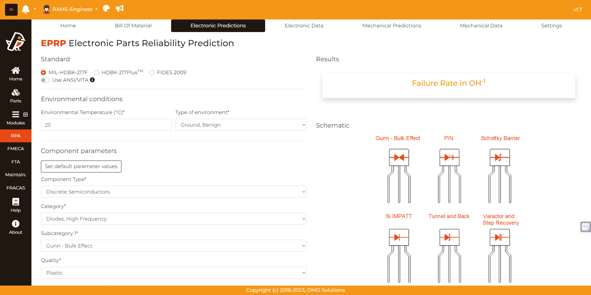
By selecting a specific component, category and subcategory, the parameters change accordingly. Furthermore, Robin provides, for each parameter:
The units which the engineer should use when entering the parameter value, on the right side
(If necessary) Additional information to clarify the meaning of the parameter or usual values, on the left side
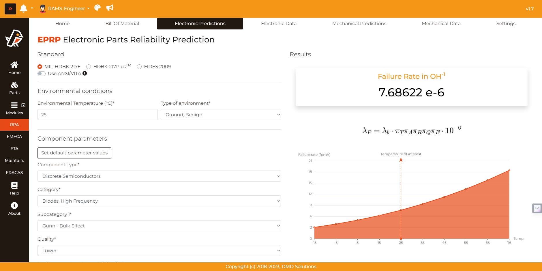
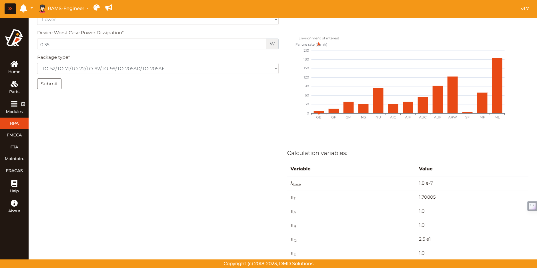
When entering all the necessary parameters, the user can compute the failure rate and the following data is obtained:
Failure rate in inverse Operating Hours
Formula applied to obtain the failure rate
Failure rate chart depending on the temperature (if applicable)
Failure rate chart depending on the environment (if applicable)
Note
The failure rate chart depends on the “Environment temperature” for the MIL-HDBK-217F Notice 2, and the “Operating Temperature” for the NSWC-11.
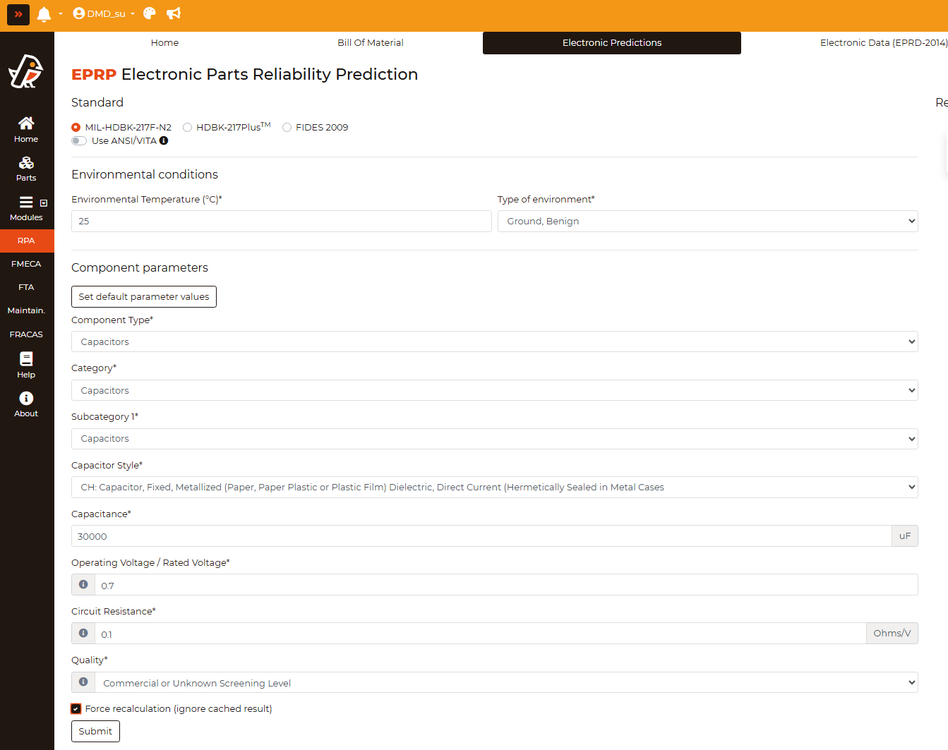
Force recalculation
When a calculation is requested for a Part Number that has already been computed before, Robin reuses the stored result instead of computing it again. This speeds up the analysis of BOMs where the same part appears many times, but it also means that a change in the environmental conditions of the page would not be reflected in the result.
The checkbox Force recalculation (ignore cached result), located at the end of the parameters form, tells Robin to discard the stored result and compute the failure rate again with the parameters currently on screen.
Note
Use this option after modifying the environmental conditions or any parameter of a part that had already been computed, to make sure the new conditions are actually applied.
Connectors: Pair and Single
For the Connectors, General category, an additional selector named Connector configuration is available with two options:
Pair: The failure rate returned by the standard corresponds to a complete connector pair. This is the default and matches the definition used by the standards.
Single: The item represents only one half of a pair, e.g. when the plug and the receptacle are listed as two separate part numbers in the BOM. In this case the failure rate obtained from the standard is divided by two:
\[\lambda_{Single} = \frac{\lambda_{P}}{2}\]
Note
Selecting Single for both halves of a connector gives the same total failure rate as listing the connector once as a Pair, while keeping both part numbers visible in the BOM.
FIDES 2009
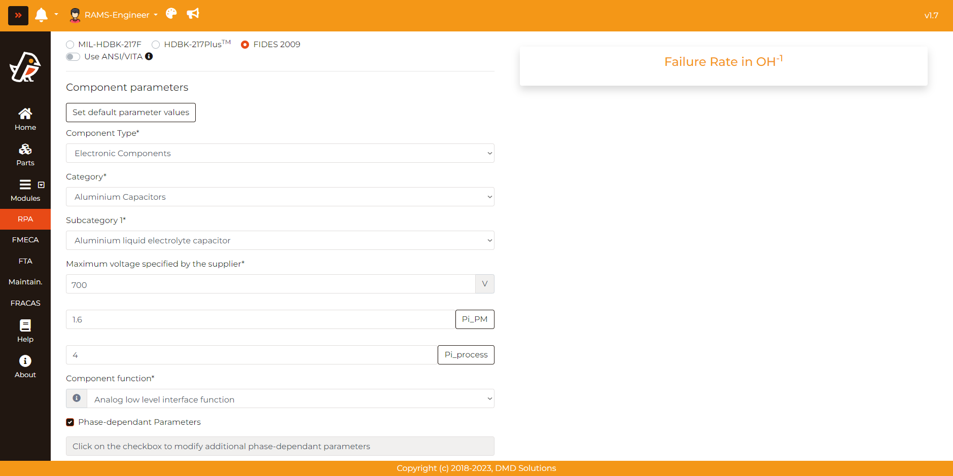
The FIDES 2009 model has specific features which make it being treated differently from other standards, as seen in the RPA > BOM. Two of its main characteristics are the prediction of the failure rate in calendar FIT and the use of special parameters (\(\pi_{PM}\) and \(\pi_{Process}\)) which are item dependent. A brief description of the FIDES special features is provided hereafter:
Failure Rate: The failure rate in the FIDES model is provided in calendar FIT (Failure in Time). Nevertheless, the model allows the conversion to failure rate expressed per hour operation, which is the output given by Robin to allow comparison between models. It is very important, then, to distinguish which of the life phases are operating phases and which are not in
RPA > BOM. To convert the failure rate in calendar hours to failure per operating hour, the following equation is used:\[\lambda_{operating} = \lambda_{calendar} \times \frac{Calendar \: duration}{Duration \: on-mission}\]Note
If non of the phases is an operating phase, the failure rate is given in calendar hours
\(\pi_{PM}\): The Part Manufacturing factor represents the item quality, and its evaluation depends on the nature of the item considered (e.g. electronic component, board assembly, etc). It can be manually introduced or, after clicking the checkbox, automatically obtained after answering a quick survey. Ranges from 0.5 to 2.
\(\pi_{Process}\) : The Process factor represents the quality and technical control over reliability in the product life cycle. It can be manually introduced or, after clicking the checkbox, automatically obtained after answer a survey. The facto ranges from 1 to 8.
Phase-dependant Parameters: When using the FIDES model, each of the life phases of an item is considered. Several magnitudes such as the average temperature or the vibration level are general magnitudes which apply to all items included in FIDES. However, there are certain components (e.g. Integrated Circuits) which require additional parameters varying from phase to phase to compute its reliability (e.g. power dissipation). In those scenarios the parameter Phase-dependant Parameters appears and, by clicking on the checkbox, the user is able to manually introduce and save them before computing the failure rate.